SUMMER LIMITED EDITION VAPES NOW AVAILABLE

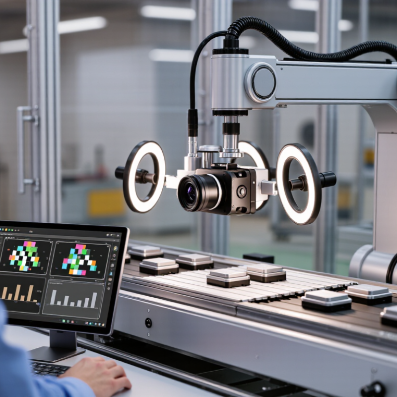
Global buyers often evaluate Machine Vision Inspection as if it were a simple camera purchase. It is not. A reliable system combines optics, lighting, sensors, software, mechanics, and production data. Each element affects the final inspection result. A scratched lens can create false defects. Uneven lighting can hide a serious flaw. Small details matter.
Dr. David Dechow, a respected machine vision and robotics specialist, describes the purpose as “imaging-based automatic inspection and analysis.” That phrase keeps the discussion practical. Buyers should examine what the system detects, how consistently it performs, and whether operators can understand its decisions. A supplier may show impressive sample images. Those images do not prove stable performance on a fast production line.
This guide presents 10 Machine Vision Inspection tips for international purchasers. It focuses on application testing, camera selection, lighting design, software capability, integration, maintenance, and supplier support. Ask for measured results. Request test samples from real production conditions. Check response times, reject accuracy, data compatibility, and service availability. Factory demonstrations can mislead when materials are unusually clean or carefully prepared. I have seen specifications look convincing before installation, yet practical limitations appeared later. That possibility deserves attention. A strong purchase decision leaves room for uncertainty, retesting, and improvement. Good inspection is not only about finding defects. It is about finding them repeatedly, clearly, and at the right production speed.
10 Machine Vision Inspection Tips for Global Buyers
Define Inspection Goals with 4 Pixels per Smallest Defect
Global automation is expanding. The International Federation of Robotics reported 541,302 industrial robot installations worldwide in 2023. More factories now depend on repeatable vision inspection, but camera selection should begin with the defect, not the camera. Define the smallest critical defect in millimeters. Then reserve at least four pixels across it. This practical rule supports stable edge detection and reduces missed defects caused by blur, vibration, or weak contrast.
For example, a 0.5 mm scratch requires approximately 0.125 mm per pixel. With a 400 mm horizontal field of view, the camera needs at least 3,200 horizontal pixels. Real production lines need margin. Lens distortion, lighting variation, and mounting tolerance consume resolution. EMVA 1288 testing principles also show why noise, dynamic range, and signal quality matter beside pixel count. I have seen teams achieve impressive laboratory images, then lose accuracy under reflective packaging. The calculation was correct. The application was not.
Tip: Measure the defect first. Keep the sample under actual line lighting. Capture dark, bright, tilted, and contaminated surfaces. Ask the integrator to document pixel coverage, exposure time, and rejection limits. A four-pixel target is only a starting point. Sometimes six or eight pixels are wiser, especially when the defect edge is irregular. Don’t optimize only for today’s sample. Future materials may challenge the original assumption.

For global buyers, sensor selection should begin with the defect, not the catalog. A 2D sensor measures contrast, width, position, and surface patterns. It suits printed codes, edge gaps, and flat parts under stable lighting. A 3D sensor captures height, depth, warpage, and volume. Use it when a two-dimensional image hides the actual failure. That choice is easy to get wrong.
Match resolution to the smallest tolerance that must be judged. If a seal gap allows ±0.20 mm, one pixel should not represent the entire tolerance. A practical starting point is four to ten pixels across the critical feature. This leaves room for noise, vibration, lens distortion, and imperfect positioning. Resolution alone cannot guarantee accuracy. Calibration, working distance, exposure, and surface finish also influence results. A shiny metal edge may appear wider after glare. Dark rubber can lose its boundary. Test real parts, including acceptable and borderline samples.
Ask suppliers for repeatability data under your actual cycle time and lighting conditions. Request measurement uncertainty, not only nominal resolution. For 3D systems, inspect height noise on flat and textured surfaces. For 2D systems, rotate parts and vary their position slightly. If pass and fail samples overlap, review the inspection limit. It may be a sensor problem, or an unclear tolerance. Factory trials often reveal another issue: higher resolution can reduce speed and coverage. A modest sensor may perform better with controlled optics and fixtures. Still, surface variation can defeat a promising setup. Build that risk into the evaluation plan.
10 Machine Vision Inspection Tips for Global Buyers
Optimize Lighting for a 10:1 Signal-to-Noise Ratio
For global buyers, reliable inspection starts with measurable lighting, not attractive sample images. A practical target is a 10:1 signal-to-noise ratio between the defect and its background. This gives the vision system enough contrast for stable decisions. Measure grayscale values across several parts, not just one perfect sample. Record brightness, variation, surface finish, and camera exposure. A matte black fixture can reduce reflected light around metal edges.
Tip: Test lighting at production speed.
Use diffuse lighting for polished surfaces and low-angle lighting for scratches or raised marks. Ring, bar, and back lighting each reveal different features. Keep the light source fixed, then adjust exposure carefully. Excessive exposure can hide small defects. Insufficient exposure creates noisy shadows. Both can produce false rejects.
Environmental control matters too. Cover nearby windows, reduce flicker, and check results during shift changes. Dust may slowly weaken contrast. Temperature can also affect some light sources and camera behavior. I have seen a setup pass daytime trials but fail under a different factory lamp. That mistake was avoidable. Repeat tests with clean, damaged, dark, bright, and borderline samples. Store the measured results with acceptance limits, so operators in different regions can verify the same standard.
| No. | Inspection Tip | Recommended Setup | Practical Target | Measurement or Validation Method | Expected Benefit |
|---|---|---|---|---|---|
| 1 | Define the defect before selecting the light | Classify the feature as a surface defect, edge, hole, printed mark, height variation, or color/contrast difference. | One primary image characteristic per inspection station. | Create a defect matrix containing at least 30 good samples and 30 representative defect samples. | Prevents unsuitable lighting geometry and reduces false rejects. |
| 2 | Optimize the signal-to-noise ratio | Adjust light angle, intensity, exposure, gain, and background so the defect signal is clearly separated from image noise. | SNR ≥ 10:1, calculated as defect signal amplitude divided by the standard deviation of background noise. | Capture repeated images of a static sample; compare the mean defect-to-background difference with background standard deviation. | Improves detection reliability and supports stable threshold settings. |
| 3 | Use diffuse lighting for uneven or reflective surfaces | Use a dome, hemispherical, or diffused panel light to reduce glare and hot spots on curved, polished, or metallic parts. | Keep pixel intensity variation across the inspection area within approximately ±10% when uniformity is required. | Measure grayscale values at the center and four corners of a uniform reference sample. | Produces more consistent images and reduces reflections caused by small part-position changes. |
| 4 | Choose low-angle dark-field lighting for scratches and raised defects | Position a narrow-beam light at a shallow angle, commonly between 10° and 30° from the inspected surface. | Make the target scratch, burr, or raised edge at least 10 gray levels above local background after exposure adjustment. | Compare defect contrast under several incidence angles using identical camera settings. | Highlights small surface changes while suppressing broad, flat areas. |
| 5 | Use backlighting for silhouettes and dimensional checks | Place a collimated or diffuse light behind the part to create a high-contrast outline. | Target an edge contrast of at least 20% of the camera's available grayscale range. | Measure edge position repeatability across 30 or more repeated captures. | Simplifies measurement of outer diameter, holes, gaps, profiles, and missing features. |
| 6 | Control exposure before increasing gain | Increase light output or exposure time first; use analog or digital gain only when necessary. | Keep important pixels away from saturation and maintain a stable histogram, typically below 95% of full scale. | Review histogram clipping and compare repeated-image standard deviation at different gain levels. | Limits amplified noise and preserves usable gray-level information. |
| 7 | Freeze motion when inspecting moving parts | Use a triggered strobe or short exposure synchronized with the conveyor or robot position. | Set exposure time so image movement is less than one pixel at the inspected feature. | At the maximum line speed, inspect edge sharpness and calculate displacement during exposure. | Reduces motion blur and improves dimensional measurement accuracy. |
| 8 | Use optical filters to remove unwanted wavelengths | Match the filter to the inspection wavelength; use a polarizer pair for glare-sensitive surfaces when polarization is suitable. | Reduce distracting background or glare intensity by at least 50% without losing the defect signal. | Compare defect contrast and background variation with the filter installed and removed. | Improves contrast in the presence of ambient light, colored backgrounds, or specular reflections. |
| 9 | Shield the inspection area from ambient light | Install a matte enclosure, light tunnel, or physical baffle around the camera and light source. | Keep ambient-light contribution below 10% of the controlled inspection signal. | Capture images with the inspection light on and off under day, night, and maintenance lighting conditions. | Protects image thresholds from changes in factory lighting and operating shifts. |
| 10 | Validate performance across production variation | Test multiple lots, part colors, surface finishes, positions, speeds, and temperatures before final approval. | Use at least 100 good parts and all known defect types, with acceptance limits defined before testing. | Record false-accept, false-reject, repeatability, and measurement results for each operating condition. | Demonstrates that the lighting design is robust for global production environments. |
| Reference note: The 10:1 signal-to-noise ratio is a practical engineering target rather than a universal pass/fail standard. Final limits should be confirmed using the smallest critical defect, the actual camera, lens, lighting, production speed, and acceptable inspection risk. | |||||
For global buyers, 1,000 labeled images should be a practical starting point, not a guarantee. Build the dataset across real production shifts, defect types, materials, camera angles, and lighting changes. A balanced sample matters more than a large image count. One thousand nearly identical images can hide serious model weaknesses.
Use trained inspectors and clear labeling rules. Record disagreements instead of deleting them. That detail often exposes unclear defect definitions. The NIST AI Risk Management Framework 1.0 recommends representative validation data, documented processes, and continuous monitoring. Independent testing should include images from a later production batch. Keep this set untouched during training.
Gauge R&R adds discipline to vision validation. Repeat the same inspection with different operators, fixtures, lighting conditions, and software runs. The AIAG Measurement Systems Analysis reference commonly treats less than 10% study variation as acceptable, while 10% to 30% may require review. These thresholds were developed for measurement systems, not every AI camera system. Use them carefully. The International Federation of Robotics reported 541,302 industrial robot installations worldwide in 2023, increasing pressure for reliable automated inspection. Yet a model can still fail on a rare scratch or reflective surface. That failure is useful evidence, not an embarrassing exception.
Global machine vision projects fail when compliance is treated as paperwork after installation. Buyers should map product safety, electrical requirements, data protection, and local documentation before selecting cameras or software. Ask suppliers for test records, calibration procedures, and change-control evidence. Keep regional settings visible.
A useful benchmark is 99.5% system uptime. That allows only about 44 hours of annual downtime. Measure more than camera availability. Track inspection delays, network interruptions, false rejects, and maintenance recovery time. Reserve replacement lighting, cables, and tested configuration files at the site. Simple spares matter.
Integration needs practical testing. Connect the vision system with conveyors, controllers, quality databases, and operator interfaces before shipment. Simulate poor lighting, damaged labels, network loss, and mixed product sizes. Record inspection speed at the slowest facility. A system that works in a laboratory may struggle beside vibration, dust, or changing operators. That lesson is easy to ignore.
Use access controls and encrypted data transfer when images leave the factory. Confirm retention periods with local teams. Translate alerts clearly, not mechanically. Train operators with real samples, including borderline defects. Audit results across locations each month. A 99.5% promise can hide weak assumptions if downtime exclusions are vague. Define every exclusion, review the numbers honestly, and revise the plan when field evidence disagrees.