SUMMER LIMITED EDITION VAPES NOW AVAILABLE


7 Tips for Choosing a Level 3 DC Fast Charging Station

Choosing a Level 3 DC fast charging station is not simply a matter of buying the highest-rated unit. A charger marked 150 kW may deliver less in practice if a vehicle cannot accept that power, the site’s electrical supply is limited, or several stalls share one power cabinet. Fatih Birol, Executive Director of the International Energy Agency, has described the broader shift this way: “The future of road transport is electric.” For station owners, that future depends on equipment that performs reliably in the real world.

The seven tips ahead focus on decisions buyers can verify: vehicle compatibility, connector options, usable charging power, site capacity, network software, service support, and room to expand. Look beyond the number on the product sheet. Ask how power is distributed when two vehicles plug in, how quickly faults are handled, and what the warranty actually covers. Check the cable reach, too; a few awkward feet can frustrate drivers every day. Small details matter.

There are trade-offs. A lower-cost unit may suit a modest site, while a busy highway location may need higher throughput and stronger service commitments. No specification guarantees uptime. That part deserves scrutiny. Use these tips to compare proposals, ask sharper questions, and choose a Level 3 DC fast charging station that fits both today’s vehicles and tomorrow’s demand.
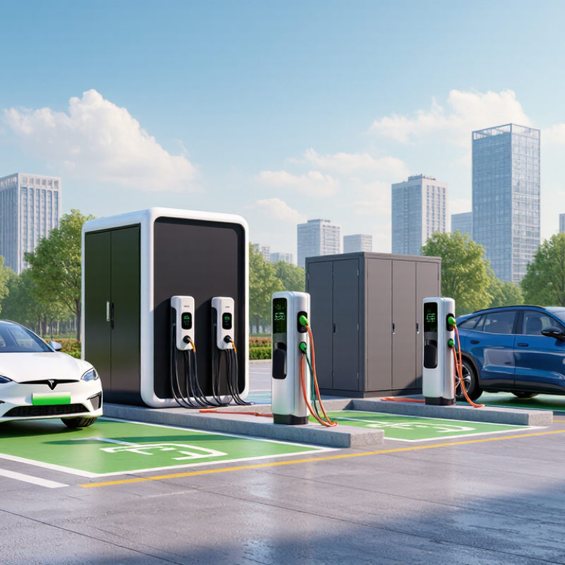
7 Tips for Choosing a Level 3 DC Fast Charging Station

Define the Use Case: Public DC Fast Chargers Commonly Deliver 50–350 kW

Tip 1: Define who will use the site and how long they are likely to stay. Public DC fast chargers commonly deliver 50–350 kW, but the highest rating is not automatically the best fit. A roadside stop may need rapid turnover, while a charger near shops can serve drivers who park longer. Match the expected dwell time to the location.

Tip 2: Check the vehicles and electrical capacity. A charger’s rated output does not guarantee that every vehicle will accept that power. Battery temperature, state of charge, and the vehicle’s own charging limit can reduce actual speed. Real-world results vary. Review local vehicle patterns and ask an electrical professional to assess available site capacity before choosing equipment.

Tip 3: Plan for busy periods, not just a quiet test. Consider how many vehicles may charge at once, whether power is shared between stalls, and where cables will reach parked cars. A 350 kW unit can be useful for compatible vehicles, but it may add cost without improving typical sessions. I would revisit that assumption after measuring demand; early estimates are often imperfect. Check access, cable handling, and service needs on site.


7 Tips for Choosing a Level 3 DC Fast Charging Station

Define the Use Case: Public DC Fast Chargers Commonly Deliver 50–350 kW

Representative public DC fast charger power ratings range from 50 kW to 350 kW. Choose a station output that fits your location, expected charging demand, and the power your vehicles can accept. Actual charging speed varies with the vehicle, battery state, and charging conditions.

Match Vehicle Compatibility: Check CCS1, NACS, CHAdeMO, and 400/800-V Systems

Tip 1: Check the vehicle’s actual inlet, not a generic “fast charging” label. CCS1, NACS (standardized as SAE J3400), and CHAdeMO are distinct DC interfaces. A physically compatible plug may still require an approved adapter and software support. Check the owner’s manual and port label. Tiny mismatch, no session.

Tip 2: Match voltage as well as connector type. A 400-V station may not deliver useful power to every 800-V vehicle. Vehicle design and the charger’s voltage range determine whether charging works and how fast. Compare the station’s minimum and maximum DC voltage with the vehicle specification. Check the charging curve, not only peak kilowatts. Peak ratings can be brief.

The IEA’s Global EV Outlook 2024 reports that public fast chargers worldwide grew by 55% in 2023, surpassing 1.3 million. More plugs mean more choice, not universal compatibility. For a site purchase, record connector types, voltage range, and tested vehicle models. Ask for commissioning records. Real tests matter. I would recheck compatibility after software updates; that step is easy to overlook.

7 Tips for Choosing a Level 3 DC Fast Charging Station - Match Vehicle Compatibility: Check CCS1, NACS, CHAdeMO, and 400/800-V Systems

Tip What to Check Compatibility Facts Practical Selection Guidance
1. Match the connector to the vehicle inlet Identify the vehicle’s DC fast-charging inlet and the connector offered by the station. CCS1, NACS (SAE J3400), and CHAdeMO are distinct charging interfaces. A plug that does not match the inlet generally requires a suitable, supported adapter. Check the vehicle manual and station connector listing before purchase or installation. Do not assume that a physically fitting adapter is approved for DC fast charging.
2. Confirm CCS1 support Verify that the vehicle uses CCS1 for DC charging and that the station provides a CCS1 cable. CCS1 combines a J1772-style upper section with two additional large DC contacts. The vehicle and charger must support the relevant charging protocol. For a mixed vehicle fleet, compare the number of CCS1 connectors with expected simultaneous charging demand.
3. Check NACS / SAE J3400 support Check the vehicle inlet standard, connector configuration, and any adapter or software requirements. SAE J3400 standardizes the NACS connector interface for AC and DC charging. Vehicle access to a particular station can still depend on vehicle configuration, network authorization, and adapter support. Confirm compatibility with the vehicle and charging network, rather than relying only on connector shape or a general NACS label.
4. Account for CHAdeMO vehicles Determine whether any vehicles that will use the site require a CHAdeMO connector. CHAdeMO is a separate DC fast-charging system. A CCS1 or NACS cable is not a direct substitute for a CHAdeMO connector. If CHAdeMO vehicles are part of the expected fleet, select equipment that explicitly lists CHAdeMO support or verify an approved alternative charging path.
5. Compare charger and vehicle voltage ranges Review the station’s DC output-voltage range and the vehicle battery’s operating voltage range. “400 V” and “800 V” describe common battery-system classes, not exact constant charging voltages. Actual voltage varies with battery state and operating conditions. Choose a station whose published output range covers the intended vehicles. A connector match alone does not establish voltage compatibility.
6. Verify 800-V charging performance Check maximum output voltage, current, and power, plus any vehicle-specific charging limitations. An 800-V-capable vehicle will not necessarily receive its maximum charging rate at every station. Some charging systems may use voltage-conversion methods that affect available power. Compare the station specifications with the vehicle’s documented fast-charging requirements; do not infer 800-V performance from a station’s maximum kilowatt rating alone.
7. Check adapters, protocol, and real-world power limits Confirm adapter approval, charging protocol support, and the station’s power-sharing behavior. Delivered power is limited by the vehicle, charger, battery temperature and state of charge, and site conditions. Shared power cabinets may divide available output among multiple active connectors. Use vehicle-approved DC adapters where applicable, confirm the station supports the vehicle’s charging protocol, and review per-connector power when multiple vehicles charge at once.

Size Site Power: Allow for Conversion Losses Beyond a Charger’s Rated kW

A Level 3 charger’s rated kilowatts describe power delivered to a vehicle, not necessarily the power drawn from the site. Conversion creates heat, and cooling systems and controls also use electricity. Plan for the charger’s input requirement, not just its headline output.

For example, a unit delivering 150 kW at 95% efficiency needs about 158 kW of input power before auxiliary loads. Efficiency changes with operating conditions, so treat this as an estimate, not a guarantee. Check the manufacturer’s technical data for maximum input current, efficiency range, and cooling demand. Small details matter.

Then assess the site’s actual electrical capacity. A panel that appears to have spare capacity may already serve lighting, HVAC, or other equipment during peak hours. Ask an electrical professional to model concurrent loads and voltage drop, and confirm what the utility can provide. Leave practical headroom for hot afternoons, future chargers, and imperfect assumptions. I would not size a site from one ideal operating figure; real usage is messier. Load management can reduce peak demand, but it cannot replace adequate wiring, protection, and available supply.

Compare Charging Curves: Battery Limits Shape 10–80% Charging Time

A Level 3 station’s peak kilowatt rating does not tell the whole charging story. Compare its power curve with the vehicle’s curve across the 10–80% state-of-charge window. The car can only draw what its battery accepts, and charging power often falls as the pack fills. Temperature matters, too. A cold battery may charge more slowly, even beside a high-output station.

The U.S. Department of Energy’s Alternative Fuels Data Center gives a broad 20-minute-to-one-hour range for DC fast charging to 80%, reflecting differences between vehicles and equipment.

Consider a 75-kWh battery: moving from 10% to 80% adds about 52.5 kWh. At a steady 150 kW, that would take roughly 21 minutes in ideal conditions. Real charging takes longer when power tapers or energy is lost.

That matters. Compare independent charging-curve tests, not just advertised peak power, and check whether the reported test began with a warm battery. A clean chart can still hide messy real-world conditions.

Plan for Growth: Evaluate OCPP 2.0.1, ISO 15118, and Power Sharing

Planning for growth starts with the charger’s communication standards, not just its maximum output. OCPP 2.0.1 can support more detailed device management, monitoring, and smart charging than older implementations. Still, protocol support on a specification sheet does not guarantee smooth operation. Ask which functions have been tested, and confirm how software updates and fault reports will be handled. Small details matter.

ISO 15118 can enable communication between a vehicle and charger, including Plug & Charge where both sides support compatible features. Check the exact implementation and test it with the vehicles expected at your site. Power sharing deserves equal attention. For example, four chargers may each advertise high output, while the site’s electrical capacity cannot supply full power to all four at once. A well-designed system can distribute available power as demand changes.

Ask what happens when one charger starts a session, another vehicle arrives, or a unit goes offline. Run through real operating scenarios with the installer. The spreadsheet may look tidy; the first busy afternoon can be less tidy. Leave room to expand, but verify that the switchgear, cabling, and site limits can support the plan.